Ethernet in Networking-
Before you go through this article, make sure that you have gone through the previous article on Ethernet.
We have discussed-
- Ethernet is one of the standard LAN technologies used to build wired LANs.
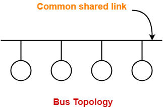
- Ethernet uses bus topology in which all the stations are connected to a half duplex link.
- Ethernet uses CSMA / CD as an access control method.
In this article, we will discuss practice problems based on Ethernet.
PRACTICE PROBLEMS BASED ON ETHERNET-
Problem-01:
Which of the following characteristic is most basic to LAN?
- Bit rate
- Delay x Bandwidth Product
- Geographical distance
- Cost
Solution-
- Geographical distance is the basic criteria on which networks are classified.
- On the basis of geographical distance, networks are classified as LAN, MAN, WAN.
- Thus,Option (C) is correct.
Problem-02:
On an Ethernet LAN when a collision is detected, the sending station-
- continues to send the transmission
- temporarily quits the transmission
- notifies the destination of an error
- permanently quits the transmission
Solution-
- Ethernet uses CSMA / CD as access control method.
- On detecting a collision, the sending station temporarily quits the transmission.
- Transmitting station waits for Back Off time and then tries again.
- Thus, Option (B) is correct.
Problem-03:
Ethernet implements _________ service for its operation.
- connection oriented
- connection less
- Both A and B
- Either A or B
Solution-
REMEMBER
|
When an Ethernet frame is sent,
- Destination is never expected to reserve the buffer or any other resource for the incoming frame.
- The data is simply dumped at the destination side.
- So, it is connectionless.
- Thus, Option (B) is correct.
Problem-04:
The collision domain of Fast Ethernet is limited to ______ meters.
- 2.5
- 25
- 250
- 2500
Solution-
- Collision domain defines the number of stations that can get involved in the collision when connected to a LAN.
- In the given question, collision domain refers to maximum distance a LAN can run to detect the collisions.
- Ethernet uses CSMA / CD as access control method.
In CSMA / CD, condition to detect collisions is-
Distance <= (Length x speed) / (2 x bandwidth)
On substituting the values, we get the value of distance.
REMEMBER
|
Thus, Option (C) is correct.
Problem-05:
The efficiency of Ethernet-
- increases when propagation delay and transmission delay are low
- increases when propagation delay and transmission delay are high
- increases when propagation delay is low and transmission delay is high
- increases when propagation delay is high and transmission delay is low
Solution-
- Efficiency of Ethernet = 1 / ( 1 + 6.44a) where a = Tp / Tt.
- Thus, Option (C) is correct.
Problem-06:
What is the baud rate of the standard 10 Mbps 802.3 LAN?
- 20 mega baud
- 10 mega baud
- 25 mega baud
- 40 mega baud
Solution-
LAN uses Manchester Encoding Technique where-
Baud rate = 2 x Bit rate
For 10 Mbps,
Baud rate
= 2 x 10 mega baud
= 20 mega baud
Thus, Option (A) is correct.
Problem-07:
Consider a 10 Mbps Ethernet LAN that has stations attached to a 2.5 km long coaxial cable. Given that the transmission speed is 2.3 x 10⁸ m/sec, the packet size is 128 bytes out of which 30 bytes are overhead, find the effective transmission rate and maximum rate at which the network can send data.
Solution-
Given-
- Bandwidth = 10 Mbps
- Distance = 2.5 km
- Transmission speed = 2.3 x 10⁸ m/sec
- Total packet size = 128 bytes
- Overhead = 30 bytes
Calculating Transmission Delay-
Transmission delay (Tt)
= Packet size / Bandwidth
= 128 bytes / 10 Mbps
= (128 x 8 bits) / (10 x 106 bits per sec)
= 1024 / 107 sec
= 102.4 μsec
Calculating Propagation Delay-
Propagation delay (Tp)
= Distance / Speed
= 2.5 km / (2.3 x 10⁸ m/sec)
= (2.5 x 10³ m) / (2.3 x 10⁸ m/sec)
= 1.08 x 10⁻⁵ sec
= 10.8 μsec
Calculating Value of ‘a’-
a
= Tp / Tt
= 10.8 μsec / 102.4 μsec
= 0.105
Calculating Efficiency-
Efficiency(η)
= 1 / (1 + 6.44 x a)
= 1 / (1 + 6.44 x 0.105)
= 1 / 1.67
= 0.59
= 59%
Calculating Maximum Rate-
Maximum rate or Throughput
= Efficiency x Bandwidth
= 0.59 x 10 Mbps
= 5.9 Mbps
Calculating Effective Transmission Rate-
Effective transmission rate
= Throughput x (128-30 / 128)
= 5.9 Mbps x (98 / 128)
= 0.77 x 5.9 Mbps
= 4.52 Mbps
Problem-08:
The following frame transition diagram shows an exchange of Ethernet frames between two computers, A and B connected via a 10BT Hub. Each frame sent by computer A contains 1500 B of Ethernet payload data, while each frame sent by computer B contains 40 B of Ethernet payload data. Calculate the average utilization of the media during this exchange.

- 10%
- 1.7%
- 20%
- 15.2%
Solution-
Calculating Data Sent By Computer A in One Frame-
Given-
- Each frame sent by computer A contains 1500 B of Ethernet payload data.
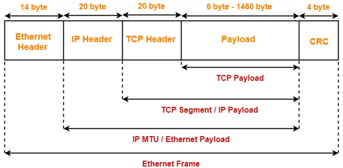
- This is divided as: 20 bytes of IP Header + 20 bytes of TCP Header + 1460 bytes of data.
So, Total bytes sent by computer A in one frame
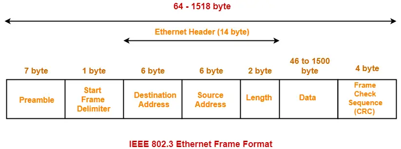
= Preamble + SFD + Ethernet Header + Ethernet Payload + CRC
= 7 bytes + 1 byte + 14 bytes + 1500 bytes + 4 bytes
= 1526 bytes
Calculating Data Sent By Computer A in 0.6 Seconds:
Computer A sends 8 frames in 0.6 seconds.
So, Total bytes sent by computer A in 0.6 seconds
= 8 x 1526 bytes
= 12208 bytes
Calculating Data Sent By Computer B in One Frame-
Given-
- Each frame sent by computer B contains 40 B of Ethernet payload data.
- This is divided as: 20 bytes of IP Header + 20 bytes of TCP Header + 0 bytes of data.
- Since minimum data in the payload field of Ethernet must 46 bytes. So, extra 6 bytes are padded.
So, Total bytes sent by computer B in one frame
= Preamble + SFD + Ethernet Header + Ethernet Payload + CRC
= 7 bytes + 1 byte + 14 bytes + (40 bytes + 6 bytes) + 4 bytes
= 72 bytes
Calculating Data Sent By Computer B in 0.6 Seconds-
Computer B sends 4 frames in 0.6 seconds.
So, Total bytes sent by computer B in 0.6 seconds
= 4 x 72 bytes
= 288 bytes
Calculating Total Data Sent in 0.6 Seconds:
Total data flow that takes place in 0.6 seconds
= Total data sent by computer A in 0.6 seconds + Total data sent by computer B in 0.6 seconds
= 12208 bytes + 288 bytes
= 12496 bytes
= 99968 bits
Calculating Throughput-
Throughput
= Amount of data that flows per second
= 99968 bits / 0.6 seconds
= 166613.33 bits/sec
Calculating Utilization-
Throughput = Efficiency x Bandwidth
So, Efficiency or Utilization
= Throughput / Bandwidth
= (166613.33 bits per sec) / 10 Mbps
= 0.017
= 1.7%
Thus, Option (B) is correct.
Problem-09:
Ethernet adaptor receives all frames and accepts-
- Frames addressed to its own address
- Frames addressed to the multicast or broadcast address
- Frames if it has been placed in promiscuous mode
- All of the above
Solution-
In a bus topology Ethernet,
- Ethernet Adaptor enables a computer to access an Ethernet Network.
- If one station sends a frame to other station, then other stations & Ethernet Adaptor also receives that frame.
- But they accept only those frames which are destined for them.
- Ethernet Adaptor accepts all those frames which are addressed to its own address or broadcast address or multicast address (if it is present in that multicast group)
- Network administrator may set the network in promiscuous mode.
- This is done to monitor the activities going on in the network.
- So, if Ethernet Adaptor is set in promiscuous mode, it receives and accepts all the frames.
- Thus, Option (D) is correct.
Next Article- Types of Switching | Circuit Switching
Get more notes and other study material of Computer Networks.
Watch video lectures by visiting our YouTube channel LearnVidFun.


