Error Detection in Computer Networks-
| Error detection is a technique that is used to check if any error occurred in the data during the transmission. |
Some popular error detection methods are-

- Single Parity Check
- Cyclic Redundancy Check (CRC)
- Checksum
In this article, we will discuss about Cyclic Redundancy Check (CRC).
Cyclic Redundancy Check-
- Cyclic Redundancy Check (CRC) is an error detection method.
- It is based on binary division.
CRC Generator-
- CRC generator is an algebraic polynomial represented as a bit pattern.
- Bit pattern is obtained from the CRC generator using the following rule-
| The power of each term gives the position of the bit and the coefficient gives the value of the bit. |
Example-
Consider the CRC generator is x7 + x6 + x4 + x3 + x + 1.
The corresponding binary pattern is obtained as-

Thus, for the given CRC generator, the corresponding binary pattern is 11011011.
Properties Of CRC Generator-
The algebraic polynomial chosen as a CRC generator should have at least the following properties-
Rule-01:
- It should not be divisible by x.
- This condition guarantees that all the burst errors of length equal to the length of polynomial are detected.
Rule-02:
- It should be divisible by x+1.
- This condition guarantees that all the burst errors affecting an odd number of bits are detected.
Important Notes-
If the CRC generator is chosen according to the above rules, then-
- CRC can detect all single-bit errors
- CRC can detect all double-bit errors provided the divisor contains at least three logic 1’s.
- CRC can detect any odd number of errors provided the divisor is a factor of x+1.
- CRC can detect all burst error of length less than the degree of the polynomial.
- CRC can detect most of the larger burst errors with a high probability.
Steps Involved-
Error detection using CRC technique involves the following steps-
Step-01: Calculation Of CRC At Sender Side-
At sender side,
- A string of n 0’s is appended to the data unit to be transmitted.
- Here, n is one less than the number of bits in CRC generator.
- Binary division is performed of the resultant string with the CRC generator.
- After division, the remainder so obtained is called as CRC.
- It may be noted that CRC also consists of n bits.
Step-02: Appending CRC To Data Unit-
At sender side,
- The CRC is obtained after the binary division.
- The string of n 0’s appended to the data unit earlier is replaced by the CRC remainder.
Step-03: Transmission To Receiver-
- The newly formed code word (Original data + CRC) is transmitted to the receiver.
Step-04: Checking at Receiver Side-
At receiver side,
- The transmitted code word is received.
- The received code word is divided with the same CRC generator.
- On division, the remainder so obtained is checked.
The following two cases are possible-
Case-01: Remainder = 0
If the remainder is zero,
- Receiver assumes that no error occurred in the data during the transmission.
- Receiver accepts the data.
Case-02: Remainder ≠ 0
If the remainder is non-zero,
- Receiver assumes that some error occurred in the data during the transmission.
- Receiver rejects the data and asks the sender for retransmission.
Also Read- Parity Check
PRACTICE PROBLEMS BASED ON CYCLIC REDUNDANCY CHECK (CRC)-
Problem-01:
A bit stream 1101011011 is transmitted using the standard CRC method. The generator polynomial is x4+x+1. What is the actual bit string transmitted?
Solution-
- The generator polynomial G(x) = x4 + x + 1 is encoded as 10011.
- Clearly, the generator polynomial consists of 5 bits.
- So, a string of 4 zeroes is appended to the bit stream to be transmitted.
- The resulting bit stream is 11010110110000.
Now, the binary division is performed as-

From here, CRC = 1110.
Now,
- The code word to be transmitted is obtained by replacing the last 4 zeroes of 11010110110000 with the CRC.
- Thus, the code word transmitted to the receiver = 11010110111110.
Problem-02:
A bit stream 10011101 is transmitted using the standard CRC method. The generator polynomial is x3+1.
- What is the actual bit string transmitted?
- Suppose the third bit from the left is inverted during transmission. How will receiver detect this error?
Solution-
Part-01:
- The generator polynomial G(x) = x3 + 1 is encoded as 1001.
- Clearly, the generator polynomial consists of 4 bits.
- So, a string of 3 zeroes is appended to the bit stream to be transmitted.
- The resulting bit stream is 10011101000.
Now, the binary division is performed as-
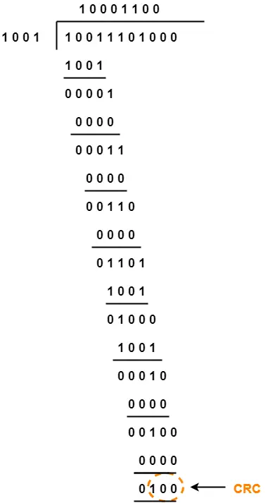
From here, CRC = 100.
Now,
- The code word to be transmitted is obtained by replacing the last 3 zeroes of 10011101000 with the CRC.
- Thus, the code word transmitted to the receiver = 10011101100.
Part-02:
According to the question,
- Third bit from the left gets inverted during transmission.
- So, the bit stream received by the receiver = 10111101100.
Now,
- Receiver receives the bit stream = 10111101100.
- Receiver performs the binary division with the same generator polynomial as-

From here,
- The remainder obtained on division is a non-zero value.
- This indicates to the receiver that an error occurred in the data during the transmission.
- Therefore, receiver rejects the data and asks the sender for retransmission.
To watch video solution, click here.
To gain better understanding about Cyclic Redundancy Check,
Next Article- Checksum
Get more notes and other study material of Computer Networks.
Watch video lectures by visiting our YouTube channel LearnVidFun.