System Bus in Computer Architecture-
What Is A System Bus?
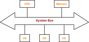
- A bus is a set of electrical wires (lines) that connects the various hardware components of a computer system.
- It works as a communication pathway through which information flows from one hardware component to the other hardware component.
| A bus that connects major components (CPU, memory and I/O devices) of a computer system is called as a System Bus. |
Why Do We Need Bus?
- A computer system is made of different components such as memory, ALU, registers etc.
- Each component should be able to communicate with other for proper execution of instructions and information flow.
- If we try to implement a mesh topology among different components, it would be really expensive.
- So, we use a common component to connect each necessary component i.e. BUS.
Components Of A System Bus-
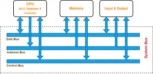
The system bus consists of three major components-
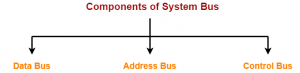
- Data Bus
- Address Bus
- Control Bus
Let us learn about each component one by one.
1) Data Bus-
- As the name suggests, data bus is used for transmitting the data / instruction from CPU to memory/IO and vice-versa.
- It is bi-directional.
Data Bus Width
Examples-
|
2) Control Bus-
- As the name suggests, control bus is used to transfer the control and timing signals from one component to the other component.
- The CPU uses control bus to communicate with the devices that are connected to the computer system.
- The CPU transmits different types of control signals to the system components.
- It is bi-directional.
What Are Control & Timing Signals?
Control signals are generated in the control unit of CPU.
Timing signals are used to synchronize the memory and I/O operations with a CPU clock.
Typical control signals hold by control bus-
- Memory read – Data from memory address location to be placed on data bus.
- Memory write – Data from data bus to be placed on memory address location.
- I/O Read – Data from I/O address location to be placed on data bus.
- I/O Write – Data from data bus to be placed on I/O address location.
Other control signals hold by control bus are interrupt, interrupt acknowledge, bus request, bus grant and several others.
The type of action taking place on the system bus is indicated by these control signals.
Example-
When CPU wants to read or write data, it sends the memory read or memory write control signal on the control bus to perform the memory read or write operation from the main memory. Similarly, when the processor wants to read from an I/O device, it generates the I/O read signal.
3) Address Bus-
- As the name suggests, address bus is used to carry address from CPU to memory/IO devices.
- It is used to identify the particular location in memory.
- It carries the source or destination address of data i.e. where to store or from where to retrieve the data.
- It is uni-directional.
Example-
When CPU wants to read or write data, it sends the memory read or memory write control signal on the control bus to perform the memory read or write operation from the main memory and the address of the memory location is sent on the address bus.
If CPU wants to read data stored at the memory location (address) 4, the CPU send the value 4 in binary on the address bus.
Address Bus Width
Examples-
|
PRACTICE PROBLEMS BASED ON SYSTEM BUS-
Problem-01:
Which of the following system bus is used to designate the source or destination of the data on the bus itself?
- Control bus
- Data bus
- Address bus
- System bus
Solution-
The correct option is (C) Address bus.
Address bus carries the source or destination address of data i.e. where to store or from where to retrieve the data.
Problem-02:
The bus which is used to transfer data from main memory to peripheral device is-
- Data bus
- Input bus
- DMA bus
- Output bus
Solution-
The correct option is (A) Data bus.
Data bus carries data / instruction from CPU to memory/IO and vice-versa.
Problem-03:
How many memory locations a system with a 32-bit address bus can address?
- 28
- 216
- 232
- 264
Solution-
The correct option is (C) 232.
232 memory locations can be addressed by a 32-bit address bus.
Problem-04:
How many bits can be transmitted at a time using a bus with 32 data lines?
- 8 bits
- 16 bits
- 32 bits
- 1024 bits
Solution-
Each line carries one bit. So, a bus with 32 data lines can transmit 32 bits at a time.
Problem-05:
A microprocessor has a data bus with 64 lines and an address bus with 32 lines. The maximum number of bits that can be stored in memory is-
- 32 x 212
- 32 x 264
- 64 x 232
- 64 x 264
Solution-
The correct option is (C) 64 x 232.
The amount of blocks that could be located is 232. Now, since data bus has 64 lines, so each block is 64 bits. Thus, maximum number of bits stored in memory is 232 x 64 bits.
Problem-06:
The address bus with a ROM of size 1024 x 8 bits is-
- 8 bits
- 10 bits
- 12 bits
- 16 bits
Solution-
The correct option is (B) 10 bits.
The size of the ROM is 1024 x 8 = 210 x 8. Here, 10 indicates the address bus and 8 indicates the data bus width.
Problem-07:
The data bus width of a ROM of size 2048 x 8 bits is-
- 8
- 10
- 12
- 16
Solution-
The correct option is (A) 8.
The size of the ROM is 2048 x 8 = 211 x 8. Here, 11 indicates the address bus and 8 indicates the data bus width.
To gain better understanding about System Bus in Computer Architecture,
Next Article- Pipelining in Computer Architecture
Get more notes and other study material of Computer Organization and Architecture.
Watch video lectures by visiting our YouTube channel LearnVidFun.