Switching in Computer Networks-
| The process of moving the data packets towards their destination by forwarding them from one port to the other port is called as switching. |
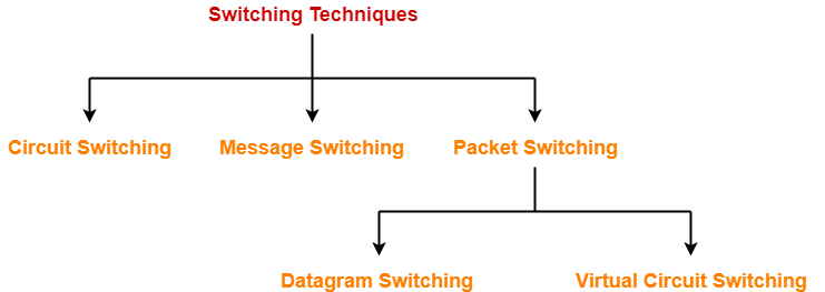
Switching Techniques-
Various switching techniques are-

- Circuit Switching
- Message Switching
- Packet Switching
In this article, we will discuss about Circuit Switching.
Circuit Switching-
This switching technique operates in the following three phases-
- Establishing a circuit
- Transferring the data
- Disconnecting the circuit
1. Establishing A Circuit-
In this phase,
- A circuit is established between the two ends.
- Circuit provides a dedicated path for data to travel from one to the other end.
- Resources are reserved at intermediate switches which are used during the transmission.
- The intermediate switches are connected by the physical links.

2. Transferring The Data-
After the circuit is established,
- The entire data travels over the dedicated path from one end to the other end.
3. Disconnecting The Circuit-
After the data transfer is completed,
- The circuit is torn down i.e. disconnected.
Total Time-
|
Total time taken to transmit a message in circuit switched network = Connection set up time + Transmission delay + Propagation delay + Tear down time |
where-
- Transmission delay = Message size / Bandwidth
- Propagation delay = (Number of hops on way x Distance between 2 hops) / Propagation speed
Also Read- Packet Switching
Advantages-
Circuit switching has the following advantages-
- A well defined and dedicated path exists for the data to travel.
- There is no header overhead.
- There is no waiting time at any switch and the data is transmitted without any delay.
- Data always reaches the other end in order.
- No re ordering is required.
Disadvantages-
Circuit switching has the following disadvantages-
- The channel is blocked for two ends only.
- It is inefficient in terms of utilization of system resources.
- The time required for establishing the circuit between the two ends is too long.
- Dedicated channels require more bandwidth.
- It is more expensive than other switching techniques.
- Routing decisions can not be changed once the circuit is established.
Important Notes-
- Circuit switching is implemented at physical layer.
- Circuit switching is now outdated.
PRACTICE PROBLEM BASED ON CIRCUIT SWITCHING TECHNIQUE-
Problem-
Consider all links in the network use TDM with 24 slots and have a data rate of 1.536 Mbps. Assume that host A takes 500 msec to establish an end to end circuit with host B before begin to transmit the file. If the file is 512 kilobytes, then how much time will it take to send the file from host A to host B?
Solution-
Given-
- Total bandwidth = 1.536 Mbps
- Bandwidth is shared among 24 slots
- Connection set up time = 500 msec
- File size = 512 KB
Calculating Bandwidth Per User-
Total bandwidth = Number of users x Bandwidth per user
So, Bandwidth per user
= Total bandwidth / Number of users
= 1.536 Mbps / 24
= 0.064 Mbps
= 64 Kbps
Calculating Transmission Delay-
Transmission delay (Tt)
= File size / Bandwidth
= 512 KB / 64 Kbps
= (512 x 210 x 8 bits) / (64 x 103 bits per sec)
= 65.536 sec
= 65536 msec
Calculating Time Required To Send File-
Time taken to send a file in circuit switched network
= Connection set up time + Transmission delay
= 500 msec + 65536 msec
= 66036 sec
= 66.036 msec
To gain better understanding about Circuit Switching,
Next Article- Message Switching
Get more notes and other study material of Computer Networks.
Watch video lectures by visiting our YouTube channel LearnVidFun.