Tag: Access Control List in Networking

Token Ring | Token Passing | Practice Problems

PRACTICE PROBLEMS BASED ON TOKEN RING AND TOKEN PASSING-


Before you go through this article, make sure that you have gone through the previous article on Token Passing.


Problem-01:


Token ring station operates in which of the following modes?

  1. Transit mode
  2. Listen mode
  3. Bypass mode and Receive mode
  4. All of the above


Solution-


  • In transmit mode, a station transmits the data.
  • In listen mode, a station listens from other station(s).
  • In bypass mode, a station simply bypasses the data packet if it is not meant for it.
  • In receive mode, a station receives the data packet if it is destined to it.

Therefore, a token ring station operates in all these modes.

Thus, Option (D) is correct.


Problem-02:


Efficiency of the token ring is high if-

  1. Reinsert the token after receiving the last bit of the frame
  2. Reinsert the token after receiving the last bit of the header
  3. Reinsert the token after last bit of the data packet is transferred
  4. Reinsert the token after last bit of the header is transferred


Solution-


  • There are two strategies used in token ring- Early Token Reinsertion (ETR) and Delayed Token Reinsertion (DTR).
  • Efficiency of token ring is high in Early Token Reinsertion (ETR).

Thus, Option (C) is correct.


Problem-03:


The sending station in IEEE 802.5 sets the address recognized (A) bit and frame copied (C) bit in MAC header as

  1. 1,0
  2. 0,0
  3. 0,1
  4. 1,1


Solution-


  • IEEE 802.5 is token ring.
  • Sending station sets both the available bit and copied bit as 0.
  • These bits are modified by the receiving station.
  • If the receiving station is available, it sets the Available bit to 1.
  • If the receiving station successfully copies the data, it sets the Copied bit to 1.

Thus, Option (B) is correct.


Problem-04:


Which of the following fields in 802.5 MAC header is not included in CRC or FCS?

  1. FC
  2. Data field
  3. FS
  4. SA


Solution-


  • IEEE 802.5 is token ring.
  • Frame Status (FS) field consists of the Available bit and Copied bit.
  • These two bits are modified by the receiving station.
  • So, CRC is not computed on Frame Status field otherwise receiving station will have to bear the overhead of recomputing the CRC.

Thus, Option (C) is correct.


Problem-05:


What type of acknowledgement system is used in 802.5?

  1. Cumulative ACK
  2. Independent ACK
  3. Piggybacking ACK
  4. None


Solution-


  • IEEE 802.5 is token ring.
  • The two bits- Available bit and Copied bit acts as the acknowledgement for the sending station.
  • The value of these bits suggests to the sending station that whether the receiving station has successfully copied the data or not.
  • Because the two bits are contained in the data frame, so we can say that piggybacked acknowledgements are used in token ring.

Thus, Option (C) is correct.


Problem-06:


In token ring, ______ field is present only in the data / command frame but not in the token frame.

  1. SD
  2. AC
  3. ED
  4. FS


Solution-


  • Frame status (FS) field is present only in the data / command frame.
  • A token frame consists of only 3 fields- SD, AC and ED.

Thus, Option (D) is correct.


Problem-07:


Consider a token ring with latency 500 μsec and packet size of 1500 bytes. What is the effective throughput rate for both single active host and for many active hosts that can be achieved if the ring has 3 Mbps bandwidth? Assume the strategy used is delayed token reinsertion.

  1. 2.4 Mbps and 3 Mbps
  2. 2.4 Mbps and 2 Mbps
  3. 2 Mbps and 3 Mbps
  4. 2.4 Mbps and 2.67 Mbps


Solution-


Given-

  • Ring latency = 500 μsec
  • Packet Size = 1500 bytes
  • Bandwidth = 3 Mbps
  • Strategy used is Delayed Token Reinsertion (DTR)


Efficiency of Delayed Token Reinsertion (DTR) strategy is-
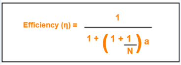


Calculating Transmission delay-


We know,

Transmission delay (Tt)

= Packet size / Bandwidth

= 1500 bytes / 3 Mbps

= (1500 x 8 bits) / (3 x 106 bits per sec)

= 4000 μsec


Calculating value of ‘a’-


We know,

a = Tp / Tt

a = Latency / Tt

a = 500 μsec / 4000 μsec

a = 0.125


Calculating Throughput for single active host-


For single active host, N = 1.

Substituting N = 1 in efficiency formula, we get-

Efficiency (η)

= 1 / (1 + 2a)

= 1 / (1 + 2 x 0.125)

= 1 / 1.25

= 0.8


Now,

Throughput

= Efficiency (η) x Bandwidth

= 0.8 x 3 Mbps

= 2.4 Mbps


Calculating Throughput for many active host-


For many active host, N = ∞.

Substituting N = ∞ in efficiency formula, we get-

Efficiency (η)

= 1 / (1 + a)

= 1 / (1 + 0.125)

= 1 / 1.125

= 0.89


Now,

Throughput

= Efficiency (η) x Bandwidth

= 0.89 x 3 Mbps

= 2.67 Mbps

Thus, Option (D) is correct.


Problem-08:


In 802.5, the condition to find out the minimum size of the ring is-

  1. Latency of the ring = Transmission delay of the data frame
  2. Latency of the ring = Transmission delay of the token frame
  3. Latency of the ring = RTT
  4. Latency > RTT


Solution-


  • IEEE 802.5 is token ring.
  • The condition to find out the minimum size of the ring is-

Latency of the ring >= Transmission delay of the token frame

  • In worst case, all the stations goes down and only the monitor station is alive.
  • Monitor station sends the token and the token comes back to it.
  • To avoid the collision between the first and the last bit of the token, propagation delay of the token must be at least equal to its transmission delay.

Thus, Option (B) is correct.


Problem-09:


The stacking station is a station in 802.5 and it can be described as-

  1. when it drains the frame and creates a token, it then stores both the old and new priority of the token
  2. A station which stack the token till it gets the last bit of the token
  3. It is nothing but monitor station
  4. None of the above


Solution-


  • IEEE 802.5 is token ring.
  • A station which increases the priority of the token should next decrease the priority of the token.
  • Otherwise once the priority of the token reaches the highest value, it would ever remain there and thus only the station with the highest packet would drain (take) the token and use it.
  • Thus, a stacking station must remember both the old and new priorities so that when it later receives the token with new priority, it changes it to old priority.
  • This is implemented by using 2 stacks. Each station maintains 2 stacks where one station keeps track of the old priority and other stack keeps track of the new priority.

Thus, Option (A) is correct.


Problem-10:


In early token release, the station releases a token as soon as it completes the frame transmission whether or not the frame header has returned to the station, then what will be the priority of the token released?

  1. The priority in the frame that completes frame transmission
  2. Without changing the priority, token will be released
  3. Default priority is used
  4. The priority in the reservation field of the most recently received frame


Solution-


Option (D) is correct.


Problem-11:


Find the efficiency of the ring where data rate of the link is 4 Mbps, number of stations are 20, separated by 100 meters and bit delay in each station is 2.5 bits. Assume early token reinsertion with packet size of 1000 bits and transmission speed is 2 x 10⁸ m/sec.


Solution-


Given-

  • Data rate = Bandwidth = 4 Mbps
  • Number of stations = 20
  • Distance between two stations = 100 meters
  • Bit delay = 25 bits
  • Packet size = 1000 bits
  • Strategy used is Early Token Reinsertion (ETR)


Calculating length of ring wire-


Total length of ring wire

= Number of stations x Distance between 2 stations

= 20 x 100 meters

= 2000 meters

= 2 km


Calculating Transmission delay-


Transmission delay (Tt)

= Packet size / Bandwidth

= 1000 bits / 4 Mbps

= 1000 bits / (4 x 106 bits per sec)

= 250 μsec


Calculating Propagation delay-


Propagation delay (Tt)

= Distance / Speed

= 2 km / (2 x 10⁸ m/sec)

= (2 x 10³ m) / (2 x 10⁸ m/sec)

= 10-5 sec

= 10 μsec


Calculating Bit delay in seconds-


Bit delay

= 25 bits

= 2.5 bits / 4 Mbps

= 25 bits / (4 x 106 bits per sec)

= 0.625 μsec


Calculating Ring latency-


Ring latency

= Propagation delay + N x Bit delay

= 10 μsec + 20 x 0.625 μsec

= 10 μsec + 12.5 μsec

= 22.5 μsec


Calculating value of ‘a’-


a

= Ring latency / Tt

= 22.5 μsec / 250 μsec

= 0.09


Calculating Efficiency-


Efficiency(η)

= 1 / (1 + a/N)

= 1 / (1 + 0.09 / 20)

= 1 / 1.0045

= 0.9955

= 99.55%


Problem-12:


A token ring LAN network interconnects M stations using Star Topology in the following way. All the input and output lines of the token ring station interface are connected to a cabinet where the actual ring is placed. Suppose that distance from each station to a cabinet is 100 m and ring latency per station is 8 bits, packets are 1250 B and bandwidth is 25 Mbps.

  1. Find the ring latency normalized to packet transmission time.
  2. Find the minimum number of packets transmitted by stations, if stations are allowed to transmit an unlimited number of packet / token. (v = 2 x 10⁸ m/sec)


Solution-


Based on the given information, the token ring LAN network looks like-
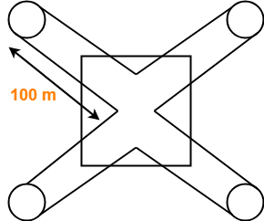
 

(The sketch is for 4 stations)


Part-01:


Calculating Transmission delay-


Transmission delay

= Packet size / Bandwidth

= 1250 B / 25 Mbps

= (1250 x 8 bits) / (25 x 106 bits per sec)

= 400 μsec


Calculating Propagation delay-


Propagation delay

= Distance / Speed

= (200 x M meters) / (2 x 10⁸ m/sec)

= (200 x M) / (2 x 10⁸) sec

= 100 x M x 10-8 sec

= M μsec


Calculating Bit delay in seconds-


Bit delay

= Ring latency per station

= 8 bits

= 8 bits / 25 Mbps

= 0.32 μsec


Calculating Ring latency-


Ring latency

= Propagation delay + N x Bit delay

= M μsec + M x 0.32 μsec

= 1.32 x M μsec


Calculating Ring latency normalized to packet transmission delay-


Ring latency normalized to packet transmission time

= Ring latency / Packet transmission time

= 1.32 x M μsec / 400 μsec

= 0.0033 x M


Part-02:


  • The number of packets a station can transmit after holding a token depends on Token Holding Time and the strategy used.
  • Since no information is given in the question about the Time Holding Time, so we assume that there is no restriction on holding the token.
  • Thus, a station can send infinite number of packets after getting a token.


Problem-13:


A very heavily loaded 1 km long, 10 Mbps token ring has a propagation speed of 200 m/μsec. 50 stations are uniformly spaced around the ring. Data frames are 256 bits including 32 bits of overhead. Acknowledgements are piggybacked onto the data frames and are thus included as spare bits within the data frames and are effectively free. The token is 8 bits long. Is the effective data rate of this ring higher or lower than the effective data rate of a 10 Mbps CSMA / CD network? Assume ‘Early Token Release’ policy.


Solution-


Remember

Token Ring always beats the Ethernet in terms of effective bandwidth.


Analysis-


Efficiency of CSMA / CD-


Efficiency of token ring in early token retransmission is given by-

Efficiency(η) = 1 / (1 + 6.44 x a)

This expression is valid when number of stations are very large i.e. N → ∞


Efficiency of Token Ring-


Case-01:


Efficiency of token ring in early token retransmission is given by-

Efficiency(η) = 1 / (1 + a/N)

When N → ∞, Efficiency(η) = 100%


Case-02:


Efficiency of token ring in delayed token retransmission is given by-

Efficiency(η) = 1 / [1 + a(1 + 1/N)]

When N → ∞, Efficiency(η) = 1 / (1+a)


The above analysis clearly shows-

Efficiency of Token Ring in ETR > Efficiency of Token Ring in DTR > Efficiency of Token Ring in CSMA / CD.


Problem-14:


A fibre optic token ring used as a MAN is 200 km long and runs at 100 Mbps. After sending a frame, a station drains the frame from the ring before regenerating the token. The signal propagation speed in the fibre is 200,000 km/sec and maximum frame size is 1 KB. What is the maximum efficiency at N=1?


Solution-


Given-

  • Distance = 200 km
  • Bandwidth = 100 Mbps
  • Propagation speed = 200,000 km/sec = 2 x 10⁸ m/sec
  • Frame size = 1 KB
  • Number of stations = 1
  • Strategy used is Delayed Token Reinsertion


Calculating Transmission delay-


Transmission delay

= Frame size / Bandwidth

= 1 KB / 100 Mbps

= (1 x 210 x 8 bits) / (100 x 106 bits per sec)

= 81.92 μsec


Calculating Propagation delay-


Propagation delay

= Distance / Speed

= 200 km / (2 x 10⁸ m/sec)

= (200 x 103 m) / (2 x 10⁸ m/sec)

= 10-3 sec

= 1 msec


Calculating value of ‘a’-


a

= Tp / Tt

= 1 msec / 81.92 μsec

= 0.0122 x 103

= 12.2


Calculating Efficiency-


Efficiency(η)

= 1 / [1 + a x (1+ 1/N)]

= 1 / [1 + 12.2 x (1+1)]

= 1 / 25.4

= 0.0394

= 3.94%


  • The reason behind this much less efficiency is that the distance is too large here.
  • Ethernet and Token Ring are meant for LANs.
  • If used for MANs or WANs, the efficiency will fall drastically.


Problem-15:


At a propagation speed of 200 m/μsec, what is the effective length added to a ring by a bit delay at each repeater or station for-

  1. 1 Mbps line
  2. 40 Mbps line


Solution-


Part-01:


Effective length added to a ring by a bit delay

= 1 bit / 1 Mbps

= 1 μsec

= 1 μsec x 200 m/μsec

= 200 m


Part-02:


Effective length added to a ring by a bit delay

= 1 bit / 40 Mbps

= 0.025 μsec

= 0.025 μsec x 200 m/μsec

= 5 m


Problem-16:


Consider a 10 Mbps token ring LAN with a ring latency of 400 μs. A host that needs to transmit seizes the toke. Then it sends a frame of 1000 bytes, removes the frame after it has circulated all around the ring and finally releases the token. This process is repeated for every frame. Assuming that only a single host wishes to transmit, the effective data rate is _____ .

  1. 1 Mbps
  2. 2 Mbps
  3. 5 Mbps
  4. 6 Mbps


Solution-


Given-

  • Bandwidth = 10 Mbps
  • Ring latency = 400 μsec
  • Frame size = 1000 bytes
  • Number of stations = 1
  • Strategy used is Delayed Toke Reinsertion


Calculating Transmission delay-


Transmission delay

= Frame size / Bandwidth

= 1000 bytes / 10 Mbps

= (1000 x 8 bits) / (10 x 106 bits per sec)

= 800 μsec


Calculating value of ‘a’-


a

= Ring latency / Tt

= 400 μsec / 800 μsec

= 0.5


Calculating Efficiency-


Efficiency(η)

= 1 / [1 + a x (1+ 1/N)]

= 1 / [1 + 0.5 x (1+1)]

= 1 / 2

= 0.50

= 50%


Calculating Effective data rate-


Effective data rate

= Throughput

= Efficiency(η) x Bandwidth

= 0.5 x 10 Mbps

= 5 Mbps

Thus, Option (C) is correct.


Next Article- Aloha | Pure Aloha | Slotted Aloha


Get more notes and other study material of Computer Networks.

Watch video lectures by visiting our YouTube channel LearnVidFun.
CSMA CD | BackOff Algorithm | Problems

CSMA / CD Protocol-


Before you go through this article, make sure that you have gone through the previous article on CSMA / CD Protocol.


We have discussed-

  • CSMA / CD allows a station to transmit data if it senses the carrier free.
  • After undergoing collision, station waits for random back off time before transmitting again.
  • Back Off Algorithm is used to calculate back off time.


Also Read- Back Off Algorithm


In this article, we will discuss practice problems based on CSMA / CD and Back Off Algorithm.


PRACTICE PROBLEMS BASED ON CSMA / CD AND BACK OFF ALGORITHM-


Problem-01:


After the kth consecutive collision, each colliding station waits for a random time chosen from the interval-

  1. (0 to 2k) x RTT
  2. (0 to 2k-1) x RTT
  3. (0 to 2k-1) x Maximum Propagation delay
  4. (0 to 2k-1) x Maximum Propagation delay


Solution-


Clearly, Option (B) is correct.


Problem-02:


In a CSMA / CD network running at 1 Gbps over 1 km cable with no repeaters, the signal speed in the cable is 200000 km/sec. What is minimum frame size?


Solution-


Given-

  • Bandwidth = 1 Gbps
  • Distance = 1 km
  • Speed = 200000 km/sec


Calculating Propagation Delay-


Propagation delay (Tp)

= Distance / Propagation speed

= 1 km / (200000 km/sec)

= 0.5 x 10⁻⁵ sec

= 5 x 10⁻⁶ sec


Calculating Minimum Frame Size-


Minimum frame size

= 2 x Propagation delay x Bandwidth

= 2 x 5 x 10-6 sec x 109 bits per sec

= 10000 bits


Problem-03:


A 2 km long broadcast LAN has 107 bps bandwidth and uses CSMA / CD. The signal travels along the wire at 2 x 10⁸ m/sec. What is the minimum packet size that can be used on this network?

  1. 50 B
  2. 100 B
  3. 200 B
  4. None of the above


Solution-


Given-

  • Distance = 2 km
  • Bandwidth = 107 bps
  • Speed = 2 x 10⁸ m/sec


Calculating Propagation Delay-


Propagation delay (Tp)

= Distance / Propagation speed

= 2 km / (2 x 10⁸ m/sec)

= 2 x 10³ m / (2 x 10⁸ m/sec)

= 10-5 sec


Calculating Minimum Frame Size-


Minimum frame size

= 2 x Propagation delay x Bandwidth

= 2 x 10-5 sec x 107 bits per sec

= 200 bits or 25 bytes


Thus, Option (D) is correct.


Problem-04:


A and B are the only two stations on Ethernet. Each has a steady queue of frames to send. Both A and B attempts to transmit a frame, collide and A wins first back off race. At the end of this successful transmission by A, both A and B attempt to transmit and collide. The probability that A wins the second back off race is ___ .

  1. 0.5
  2. 0.625
  3. 0.75
  4. 1.0


Solution-


According to question, we have-


1st Transmission Attempt-


  • Both the stations A and B attempts to transmit a frame.
  • A collision occurs.
  • Back Off Algorithm runs.
  • Station A wins and successfully transmits its 1st data packet.


2nd Transmission Attempt-


  • Station A attempts to transmit its 2nd data packet.
  • Station B attempts to retransmit its 1st data packet.
  • A collision occurs.


Now,

  • We have been asked the probability of station A to transmit its 2nd data packet successfully after 2nd collision.
  • After the 2nd collision occurs, we have-


At Station A-


  • 2nd data packet of station A undergoes collision for the 1st time.
  • So, collision number for the 2nd data packet of station A = 1.
  • Now, station A randomly chooses a number from the range [0,21-1] = [0,1].
  • Then, station A waits for back off time and then attempts to retransmit its data packet.


At Station B-


  • 1st data packet of station B undergoes collision for the 2nd time.
  • So, collision number for the 1st data packet of station B = 2.
  • Now, station B randomly chooses a number from the range [0,22-1] = [0,3].
  • Then, station B waits for back off time and then attempts to retransmit its data packet.


Following 8 cases are possible-


Station A Station B Remark
0 0 Collision
0 1 A wins
0 2 A wins
0 3 A wins
1 0 B wins
1 1 Collision
1 2 A wins
1 3 A wins


From here,

  • Probability of A winning the 2nd back off race = 5 / 8 = 0.625.
  • Thus, Option (B) is correct.


Problem-05:


Suppose nodes A and B are on same 10 Mbps Ethernet segment and the propagation delay between two nodes is 225 bit times. Suppose A and B send frames at t=0, the frames collide then at what time, they finish transmitting a jam signal. Assume a 48 bit jam signal.


Solution-


Propagation delay (Tp)

= 225 bit times

= 225 bit / 10 Mbps

= 22.5 x 10⁻⁶ sec

= 22.5 μsec


At t = 0,


  • Nodes A and B start transmitting their frame.
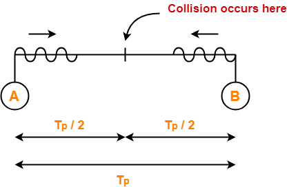
  • Since both the stations start simultaneously, so collision occurs at the mid way.
  • Time after which collision occurs = Half of propagation delay.
  • So, time after which collision occurs = 22.5 μsec / 2 = 11.25 μsec.


At t = 11.25 μsec,


  • After collision occurs at t = 11.25 μsec, collided signals start travelling back.
  • Collided signals reach the respective nodes after time = Half of propagation delay
  • Collided signals reach the respective nodes after time = 22.5 μsec / 2 = 11.25 μsec.
  • Thus, at t = 22.5 μsec, collided signals reach the respective nodes.


At t = 22.5 μsec,


  • As soon as nodes discover the collision, they immediately release the jam signal.
  • Time taken to finish transmitting the jam signal = 48 bit time = 48 bits/ 10 Mbps = 4.8 μsec.


Thus,

Time at which the jam signal is completely transmitted

= 22.5 μsec + 4.8 μsec

= 27.3 μsec or 273 bit times


Problem-06:


Suppose nodes A and B are attached to opposite ends of the cable with propagation delay of 12.5 ms. Both nodes attempt to transmit at t=0. Frames collide and after first collision, A draws k=0 and B draws k=1 in the exponential back off protocol. Ignore the jam signal. At what time (in seconds), is A’s packet completely delivered at B if bandwidth of the link is 10 Mbps and packet size is 1000 bits.


Solution-


Given-

  • Propagation delay = 12.5 ms
  • Bandwidth = 10 Mbps
  • Packet size = 1000 bits


Time At Which Collision Occurs-


Collision occurs at the mid way after time

= Half of Propagation delay

= 12.5 ms / 2

= 6.25 ms

Thus, collision occurs at time t = 6.25 ms.


Time At Which Collision is Discovered-


Collision is discovered in the time it takes the collided signals to reach the nodes

= Half of Propagation delay

= 12.5 ms / 2

= 6.25 ms

Thus, collision is discovered at time t = 6.25 ms + 6.25 ms = 12.5 ms.


Scene After Collision-


After the collision is discovered,

  • Both the nodes wait for some random back off time.
  • A chooses k=0 and then waits for back off time = 0 x 25 ms = 0 ms.
  • B chooses k=1 and then waits for back off time = 1 x 25 ms = 25 ms.
  • From here, A begins retransmission immediately while B waits for 25 ms.


Waiting Time For A-


  • After winning the back off race, node A gets the authority to retransmit immediately.
  • But node A does not retransmit immediately.
  • It waits for the channel to clear from the last bit aborted by it on discovering the collision.
  • Time taken by the last bit to get off the channel = Propagation delay = 12.5 ms.
  • So, node A waits for time = 12.5 ms and then starts the retransmission.
  • Thus, node A starts the retransmission at time t = 12.5 ms + 12.5 ms = 25 ms.


Time Taken in Delivering Packet To Node B-


Time taken to deliver the packet to node B

= Transmission delay + Propagation delay

= (1000 bits / 10 Mbps) + 12.5 ms

= 100 μs + 12.5 ms

= 0.1 ms + 12.5 ms

= 12.6 ms


Thus, At time t = 25 ms + 12.6 ms = 37.6 ms, the packet is delivered to node B.


Problem-07:


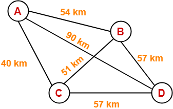
The network consists of 4 hosts distributed as shown below-


Assume this network uses CSMA / CD and signal travels with a speed of 3 x 10⁵ km/sec. If sender sends at 1 Mbps, what could be the minimum size of the packet?

  1. 600 bits
  2. 400 bits
  3. 6000 bits
  4. 1500 bits


Solution-


  • CSMA / CD is a Access Control Method.
  • It is used to provide the access to stations to a broadcast link.
  • In the given network, all the links are point to point.
  • So, there is actually no need of implementing CSMA / CD.
  • Stations can transmit whenever they want to transmit.


In CSMA / CD,

The condition to detect collision is-

Packet size >= 2 x (distance / speed) x Bandwidth


To solve the question,

  • We assume that a packet of same length has to be used in the entire network.
  • To get the minimum length of the packet, what distance we should choose?
  • To get the minimum length of the packet, we should choose the minimum distance.
  • But, then collision would be detected only in the links having distance less than or equal to that minimum distance.
  • For the links, having distance greater than the minimum distance, collision would not be detected.
  • So, we choose the maximum distance so that collision can be detected in all the links of the network.


So, we use the values-

  • Distance = 90 km
  • Speed = 3 x 10⁵ km/sec
  • Bandwidth = 1 Mbps


Substituting these values, we get-

Minimum size of data packet

= 2 x (90 km / 3 x 10⁵ km per sec) x 1 Mbps

= 2 x 30 x 10-5 sec x 106 bits per sec

= 600 bits


Thus, Option (A) is correct.


Next Article- Token Passing | Access Control Method


Get more notes and other study material of Computer Networks.

Watch video lectures by visiting our YouTube channel LearnVidFun.
Aloha | Pure Aloha | Slotted Aloha

Access Control in Networking-


Before you go through this article, make sure that you have gone through the previous article on Access Control.


We have discussed-

  • Access Control is a mechanism that controls the access of stations to the transmission link.
  • Broadcast links require the access control mechanism.
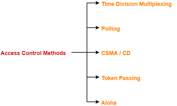
  • There are various access control methods-


  1. Time Division Multiplexing
  2. Polling
  3. CSMA / CD
  4. Token Passing
  5. Aloha


In this article, we will discuss about Aloha and its versions.


Aloha-


There are two different versions of Aloha-


  1. Pure Aloha
  2. Slotted Aloha


1. Pure Aloha-


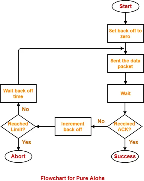
  • It allows the stations to transmit data at any time whenever they want.
  • After transmitting the data packet, station waits for some time.


Then, following 2 cases are possible-


Case-01:


  • Transmitting station receives an acknowledgement from the receiving station.
  • In this case, transmitting station assumes that the transmission is successful.


Case-02:


  • Transmitting station does not receive any acknowledgement within specified time from the receiving station.
  • In this case, transmitting station assumes that the transmission is unsuccessful.


Then,

  • Transmitting station uses a Back Off Strategy and waits for some random amount of time.
  • After back off time, it transmits the data packet again.
  • It keeps trying until the back off limit is reached after which it aborts the transmission.


Efficiency-


Efficiency of Pure Aloha (η) = G x e-2G


where G = Number of stations willing to transmit data


Maximum Efficiency-


For maximum efficiency,

  • We put dη / dG = 0
  • Maximum value of η occurs at G = 1/2
  • Substituting G = 1/2 in the above expression, we get-


Maximum efficiency of Pure Aloha

= 1/2 x e-2 x 1/2

= 1 / 2e

= 0.184

= 18.4%


Thus,


Maximum Efficiency of Pure Aloha (η) = 18.4%


The maximum efficiency of Pure Aloha is very less due to large number of collisions.


2. Slotted Aloha-


  • Slotted Aloha divides the time of shared channel into discrete intervals called as time slots.
  • Any station can transmit its data in any time slot.
  • The only condition is that station must start its transmission from the beginning of the time slot.
  • If the beginning of the slot is missed, then station has to wait until the beginning of the next time slot.
  • A collision may occur if two or more stations try to transmit data at the beginning of the same time slot.


Efficiency-


Efficiency of Slotted Aloha (η) = G x e-G


where G = Number of stations willing to transmit data at the beginning of the same time slot


Maximum Efficiency-


For maximum efficiency,

  • We put dη / dG = 0
  • Maximum value of η occurs at G = 1
  • Substituting G = 1 in the above expression, we get-


Maximum efficiency of Slotted Aloha

= 1 x e-1

= 1 / e

= 0.368

= 36.8%


Thus,


Maximum Efficiency of Slotted Aloha (η) = 36.8%


The maximum efficiency of Slotted Aloha is high due to less number of collisions.


Difference Between Pure Aloha And Slotted Aloha-


Pure Aloha Slotted Aloha
Any station can transmit the data at any time. Any station can transmit the data at the beginning of any time slot.
The time is continuous and not globally synchronized. The time is discrete and globally synchronized.
Vulnerable time in which collision may occur

= 2 x Tt

Vulnerable time in which collision may occur

= Tt

Probability of successful transmission of data packet

= G x e-2G

Probability of successful transmission of data packet

= G x e-G

Maximum efficiency = 18.4%

(Occurs at G = 1/2)

Maximum efficiency = 36.8%

( Occurs at G = 1)

The main advantage of pure aloha is its simplicity in implementation. The main advantage of slotted aloha is that it reduces the number of collisions to half and doubles the efficiency of pure aloha.


PRACTICE PROBLEM BASED ON PURE ALOHA AND SLOTTED ALOHA-


Problem-


A group of N stations share 100 Kbps slotted ALOHA channel. Each station output a 500 bits frame on an average of 5000 ms even if previous one has not been sent. What is the required value of N?


Solution-


Throughput Of One Station-


Throughput of each station

= Number of bits sent per second

= 500 bits / 5000 ms

= 500 bits / (5000 x 10-3 sec)

= 100 bits/sec


Throughput Of Slotted Aloha-


Throughput of slotted aloha

= Efficiency x Bandwidth

= 0.368 x 100 Kbps

= 36.8 Kbps


Total Number Of Stations-


Throughput of slotted aloha = Total number of stations x Throughput of each station

Substituting the values, we get-

36.8 Kbps = N x 100 bits/sec

∴ N = 368

Thus, required value of N = 368.


To gain better understanding about Aloha,

Watch this Video Lecture


Next Article- Ethernet | Ethernet Frame Format


Get more notes and other study material of Computer Networks.

Watch video lectures by visiting our YouTube channel LearnVidFun.
Token Passing | Token Ring in Networking

Access Control in Networking-


Before you go through this article, make sure that you have gone through the previous article on Access Control.


We have discussed-

  • Access Control is a mechanism that controls the access of stations to the transmission link.
  • Broadcast links require the access control mechanism.
  • There are various access control methods-


  1. Time Division Multiplexing
  2. Polling
  3. CSMA / CD
  4. Token Passing
  5. Aloha


In this article, we will discuss about Token Passing.


Before discussing Token Passing, let us discuss few important concepts required for the discussion.


Time Conversions-


In token passing,

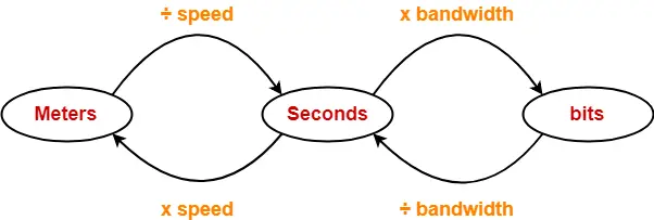
  • Time may be expressed in seconds, bits or meters.
  • To convert the time from one unit to another, we use the following conversion chart-


Conversion Chart


Token Passing Terminology-


The following terms are frequently used-

  1. Token
  2. Ring Latency
  3. Cycle Time


1. Token-


  • A token is a small message composed of a special bit pattern.
  • It represents the permission to send the data packet.
  • A station is allowed to transmit a data packet if and only if it possess the token otherwise not.


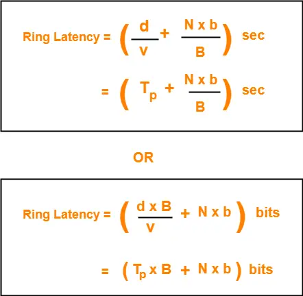
2. Ring Latency-


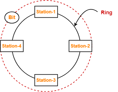
Time taken by a bit to complete one revolution of the ring is called as ring latency.


Let us derive the expression for ring latency.

If-

  • Length of the ring = d
  • Speed of the bit = v
  • Number of stations = N
  • Bit delay at each station = b

(Bit delay is the time for which a station holds the bit before transmitting to the other side)

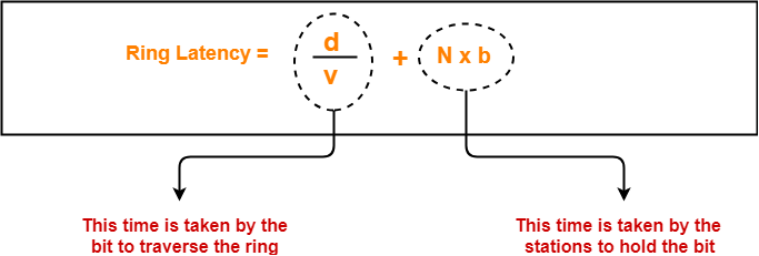
Then-


Notes-


  • d / v is the propagation delay (Tp) expressed in seconds.
  • Generally, bit delay is expressed in bits.
  • So, both the terms (d / v and N x b) have different units.
  • While calculating the ring latency, both the terms are brought into the same unit.
  • The above conversion chart is used for conversion.


After conversion, we have-


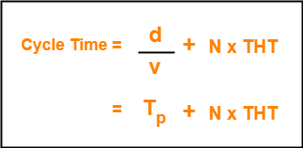
3. Cycle Time-


Time taken by the token to complete one revolution of the ring is called as cycle time.


If-

  • Length of the ring = d
  • Speed of the bit = v
  • Number of stations = N
  • Token Holding Time = THT

(Token Holding Time is the time for which a station holds the token before transmitting to the other side)

Then-


Now, we start discussing about Token Passing Access Control Method.


Token Passing-


In this access control method,

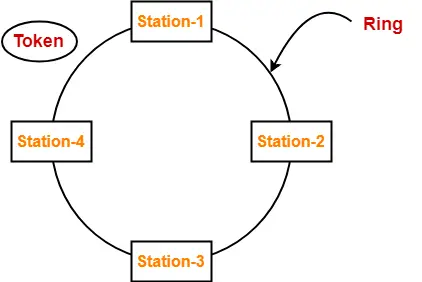
  • All the stations are logically connected to each other in the form of a ring.
  • The access of stations to the transmission link is governed by a token.
  • A station is allowed to transmit a data packet if and only if it possess the token otherwise not.
  • Each station passes the token to its neighboring station either clockwise or anti-clockwise.


Assumptions-


Token passing method assumes-

  • Each station in the ring has the data to send.
  • Each station sends exactly one data packet after acquiring the token.


Efficiency-


Efficiency (η) = Useful Time / Total Time


In one cycle,

  • Useful time = Sum of transmission delay of N stations since each station sends 1 data packet = N x Tt
  • Total Time = Cycle time = Tp + N x THT

Thus,


Token Holding Time depends on the strategy implemented.


Token Passing Strategies-


The following 2 strategies are used in token passing-


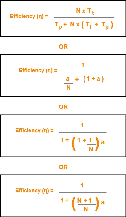
  1. Delayed Token Reinsertion (DTR)
  2. Early Token Reinsertion (ETR)


1. Delayed Token Reinsertion-


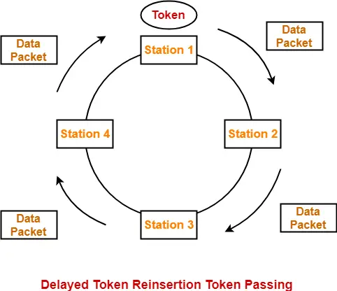
In this strategy,

  • Station keeps holding the token until the last bit of the data packet transmitted by it takes the complete revolution of the ring and comes back to it.


Working-


After a station acquires the token,

  • It transmits its data packet.
  • It holds the token until the data packet reaches back to it.
  • After data packet reaches to it, it discards its data packet as its journey is completed.
  • It releases the token.


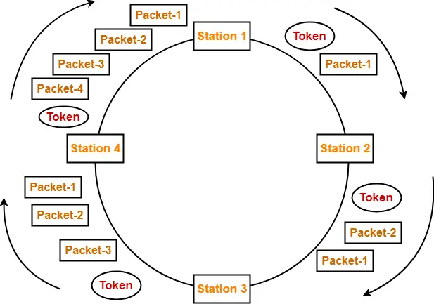
The following diagram illustrates these steps for station-1. Same procedure is repeated at every station.


Token Holding Time-


Token Holding Time (THT) = Transmission delay + Ring Latency


We know,

  • Ring Latency = Tp + N x bit delay
  • Assuming bit delay = 0 (in most cases), we get-


Token Holding Time = Tt + Tp


Efficiency-


Substituting THT = Tt + Tp in the efficiency expression, we get-


2. Early Token Reinsertion-


In this strategy,

  • Station releases the token immediately after putting its data packet to be transmitted on the ring.


Working-


Step-01: At Station-1:


Station-1

  • Acquires the token
  • Transmits packet-1
  • Releases the token


Step-02: At Station-2:


Station-2

  • Receives packet-1
  • Transmits packet-1
  • Acquires the token
  • Transmits packet-2
  • Releases the token


Step-03: At Station-3:


Station-3

  • Receives packet-1
  • Transmits packet-1
  • Receives packet-2
  • Transmits packet-2
  • Acquires the token
  • Transmits packet-3
  • Releases the token


Step-04: At Station-4:


Station-4

  • Receives packet-1
  • Transmits packet-1
  • Receives packet-2
  • Transmits packet-2
  • Receives packet-3
  • Transmits packet-3
  • Acquires the token
  • Transmits packet-4
  • Releases the token


Step-05: At Station-1:


  • Receives packet-1
  • Discards packet-1 (as its journey is completed)
  • Receives packet-2
  • Transmits packet-2
  • Receives packet-3
  • Transmits packet-3
  • Receives packet-4
  • Transmits packet-4
  • Acquires the token
  • Transmits packet-1 (new)
  • Releases the token

In this manner, the cycle continues.


Token Holding Time-


Token Holding Time (THT) = Transmission delay of data packet = Tt


Efficiency-


Substituting THT = Tt in the efficiency expression, we get-


Differences between DTR and ETR-


Delay Token Retransmission (DTR) Early Token Retransmission (ETR)
Each station holds the token until its data packet reaches back to it. Each station releases the token immediately after putting its data packet on the ring.
There exists only one data packet on the ring at any given instance. There exists more than one data packet on the ring at any given instance.
It is more reliable than ETR. It is less reliable than DTR.
It has low efficiency as compared to ETR. It has high efficiency as compared to ETR.


Important Notes-


Note-01:


In token passing,

  • It is the responsibility of each transmitting station to remove its own data packet from the ring.


Note-02:


While solving questions,

  • If the strategy used is not mentioned, then consider Early Token Retransmission strategy.


To gain better understanding about Token Passing Method,

Watch this Video Lecture


Next Article- Practice Problems On Token Passing


Get more notes and other study material of Computer Networks.

Watch video lectures by visiting our YouTube channel LearnVidFun.

Binary Exponential BackOff Algorithm | CSMA CD

CSMA / CD Protocol-


Before you go through this article, make sure that you have gone through the previous article on CSMA / CD Protocol.


We have discussed-

  • CSMA / CD stands for Carrier Sense Multiple Access / Collision Detection.
  • It allows the stations to sense the carrier and transmit data if the carrier is free.


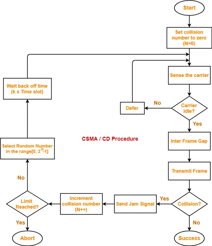
The following CSMA / CD flowchart shows the CSMA / CD procedure-


Back Off Time-


In CSMA / CD protocol,

  • After the occurrence of collision, station waits for some random back off time and then retransmits.
  • This waiting time for which the station waits before retransmitting the data is called as back off time.
  • Back Off Algorithm is used for calculating the back off time.


Back Off Algorithm-


After undergoing the collision,

  • Transmitting station chooses a random number in the range [0, 2n-1] if the packet is undergoing collision for the nth time.
  • If station chooses a number k, then-


Back off time = k x Time slot

where value of one time slot = 1 RTT


Example-


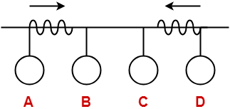
Consider the following scenario where stations A and D start transmitting their data simultaneously-


For simplicity,

  • We consider the value of time slot = 1 unit.
  • Thus, back off time = K units.


Scene-01: For 1st Data Packet Of Both Stations-


  • Both the stations start transmitting their 1st data packet simultaneously.
  • This leads to a collision.
  • Clearly, the collision on both the packets is occurring for the 1st time.
  • So, collision number for the 1st data packet of both the stations = 1.


At Station A-


After detecting the collision,

  • Station A randomly chooses a number in the range [0, 21-1] = [0,1].
  • If station A chooses the number KA, then back off time = KA units.


At Station D-


After detecting the collision,

  • Station D randomly chooses a number in the range [0, 21-1] = [0,1].
  • If station D chooses the number KD, then back off time = KD units.


Following 4 cases are possible-


KA KD Remarks
0 0
  • In this case, both the stations start retransmitting their data immediately.
  • This case leads to a collision again.
0 1
  • In this case, station A starts retransmitting its data immediately while station D waits for 1 unit of time.
  • This case leads to A successfully retransmitting its data after the 1st collision.
1 0
  • In this case, station A waits for 1 unit of time while station D starts retransmitting its data immediately.
  • This case leads to D successfully retransmitting its data after the 1st collision.
1 1
  • In this case, both the stations wait for 1 unit of time and then starts retransmitting their data simultaneously.
  • This case leads to a collision again.


From here,

  • Probability of station A to successfully retransmit its data after the 1st collision = 1 / 4
  • Probability of station D to successfully retransmit its data after the 1st collision = 1 / 4
  • Probability of occurrence of collision again after the 1st collision = 2 / 4 = 1 / 2


Now,

  • Consider case-02 occurs.
  • This causes station A to successfully retransmit its 1st packet after the 1st collision.


Scene-02: For 2nd Data Packet Of Station A And 1st Data Packet Of Station D-


Consider after some time,

  • Station A starts transmitting its 2nd data packet and station D starts retransmitting its 1st data packet simultaneously.
  • This leads to a collision.


At Station A-


  • The 2nd data packet of station A undergoes collision for the 1st time.
  • So, collision number for the 2nd data packet of station A = 1.
  • Now, station A randomly chooses a number in the range [0, 21-1] = [0,1].
  • If station A chooses the number KA, then back off time = KA units.


At Station D-


  • The 1st data packet of station D undergoes collision for the 2nd time.
  • So, collision number for the 1st data packet of station D = 2.
  • Now, station D randomly chooses a number in the range [0, 22-1] = [0,3].
  • If station D chooses the number KD, then back off time = KD units.


Following 8 cases are possible-


KA KD Remarks
0 0
  • In this case, both the stations start retransmitting their data immediately.
  • This case leads to a collision again.
0 1
  • In this case, station A starts retransmitting its data immediately while station D waits for 1 unit of time.
  • This case leads to A successfully retransmitting its data after the 2nd collision.
0 2
  • In this case, station A starts retransmitting its data immediately while station D waits for 2 unit of time.
  • This case leads to A successfully retransmitting its data after the 2nd collision.
0 3
  • In this case, station A starts retransmitting its data immediately while station D waits for 3 unit of time.
  • This case leads to A successfully retransmitting its data after the 2nd collision.
1 0
  • In this case, station A waits for 1 unit of time while station D starts retransmitting its data immediately.
  • This case leads to D successfully retransmitting its data after the 2nd collision.
1 1
  • In this case, both the stations wait for 1 unit of time and then starts retransmitting their data simultaneously.
  • This case leads to a collision again.
1 2
  • In this case, station A waits for 1 unit of time while station D waits for 2 unit of time.
  • This case leads to A successfully retransmitting its data after the 2nd collision.
1 3
  • In this case, station A waits for 1 unit of time while station D waits for 3 unit of time.
  • This case leads to A successfully retransmitting its data after the 2nd collision.


From here,

  • Probability of station A to successfully retransmit its data after the 2nd collision = 5 / 8
  • Probability of station D to successfully retransmit its data after the 2nd collision = 1 / 8
  • Probability of occurrence of collision again after the 2nd collision = 2 / 8 = 1 / 4


Now,

  • Consider case-03 occurs.
  • This causes station A to successfully retransmit its 2nd packet after the 2nd collision.


Scene-03: For 3rd Data Packet Of Station A And 1st Data Packet Of Station D-


Consider after some time,

  • Station A starts transmitting its 3rd data packet and station D starts retransmitting its 1st data packet simultaneously.
  • This leads to a collision.


At Station A-


  • The 3rd data packet of station A undergoes collision for the 1st time.
  • So, collision number for the 3rd data packet of station A = 1.
  • Now, station A randomly chooses a number in the range [0, 21-1] = [0,1].
  • If station A chooses the number KA, then back off time = KA unit.


At Station D-


  • The 1st data packet of station D undergoes collision for the 3rd time.
  • So, collision number for the 1st data packet of station D = 3.
  • Now, station D randomly chooses a number in the range [0, 23-1] = [0,7].
  • If station D chooses the number KD, then back off time = KD unit.


Following 16 cases are possible-


KA KD Remarks
0 0
  • In this case, both the stations start retransmitting their data immediately.
  • This case leads to a collision again.
0 1
  • In this case, station A starts retransmitting its data immediately while station D waits for 1 unit of time.
  • This case leads to A successfully retransmitting its data after the 3rd collision.
0 2
  • In this case, station A starts retransmitting its data immediately while station D waits for 2 unit of time.
  • This case leads to A successfully retransmitting its data after the 3rd collision.
0 3
  • In this case, station A starts retransmitting its data immediately while station D waits for 3 unit of time.
  • This case leads to A successfully retransmitting its data after the 3rd collision.
0 4
  • In this case, station A starts retransmitting its data immediately while station D waits for 4 unit of time.
  • This case leads to A successfully retransmitting its data after the 3rd collision.
0 5
  • In this case, station A starts retransmitting its data immediately while station D waits for 5 unit of time.
  • This case leads to A successfully retransmitting its data after the 3rd collision.
0 6
  • In this case, station A starts retransmitting its data immediately while station D waits for 6 unit of time.
  • This case leads to A successfully retransmitting its data after the 3rd collision.
0 7
  • In this case, station A starts retransmitting its data immediately while station D waits for 7 unit of time.
  • This case leads to A successfully retransmitting its data after the 3rd collision.
1 0
  • In this case, station A waits for 1 unit of time while station D starts retransmitting its data immediately.
  • This case leads to D successfully retransmitting its data after the 3rd collision.
1 1
  • In this case, both the stations wait for 1 unit of time and then starts retransmitting their data simultaneously.
  • This case leads to a collision again.
1 2
  • In this case, station A waits for 1 unit of time while station D waits for 2 unit of time.
  • This case leads to A successfully retransmitting its data after the 3rd collision.
1 3
  • In this case, station A waits for 1 unit of time while station D waits for 3 unit of time.
  • This case leads to A successfully retransmitting its data after the 3rd collision.
1 4
  • In this case, station A waits for 1 unit of time while station D waits for 4 unit of time.
  • This case leads to A successfully retransmitting its data after the 3rd collision.
1 5
  • In this case, station A waits for 1 unit of time while station D waits for 5 unit of time.
  • This case leads to A successfully retransmitting its data after the 3rd collision.
1 6
  • In this case, station A waits for 1 unit of time while station D waits for 6 unit of time.
  • This case leads to A successfully retransmitting its data after the 3rd collision.
1 7
  • In this case, station A waits for 1 unit of time while station D waits for 7 unit of time.
  • This case leads to A successfully retransmitting its data after the 3rd collision.


From here,

  • Probability of station A to successfully retransmit its data after the 3rd collision = 13 / 16
  • Probability of station D to successfully retransmit its data after the 3rd collision = 1 / 16
  • Probability of occurrence of collision again after the 3rd collision = 1 / 16


In the similar manner, the procedure continues.


Important Notes-


Note-01:


With each successive collision-

  • Back off time increases exponentially.
  • Collision probability decreases exponentially.


Note-02:


Back Off Algorithm is also known as Binary Exponential Back Off Algorithm because-

  • It works for only two stations.
  • The back off time increases exponentially.
  • Collision probability decreases exponentially.


Note-03:


  • One disadvantage of Back Off Algorithm is that it shows capture effect.
  • It means if a particular station wins the collision one time, then its probability of winning the successive collisions increases exponentially.


To gain better understanding about Back Off Algorithm,

Watch this Video Lecture


Next Article- Practice Problems On CSMA / CD & Back Off Algorithm


Get more notes and other study material of Computer Networks.

Watch video lectures by visiting our YouTube channel LearnVidFun.