Local Area Network-
- A Local Area Network (LAN) is a network of computers.
- It is confined to a small area which may be a room, building or a group of buildings.
- A LAN may be wired, wireless or a combination of the two.
LAN Technologies-
Standard technologies used to build a wired LAN are-

- Ethernet
- Token Ring
In this article, we will discuss about Ethernet and its Frame Format.
Ethernet-
- Ethernet is one of the standard LAN technologies used for building wired LANs.
- It is defined under IEEE 802.3.
Characteristics-
Point-01:
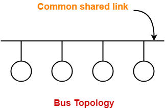
- Ethernet uses bus topology.
- In bus topology, all the stations are connected to a single half duplex link.

Point-02:
- Ethernet uses CSMA / CD as access control method to deal with the collisions.
Point-03:
- Ethernet uses Manchester Encoding Technique for converting data bits into signals.
Point-04:
- For Normal Ethernet, operational bandwidth is 10 Mbps.
- For Fast Ethernet, operational bandwidth is 100 Mbps.
- For Gigabit Ethernet, operational bandwidth is 1 Gbps.
Ethernet Frame Format-
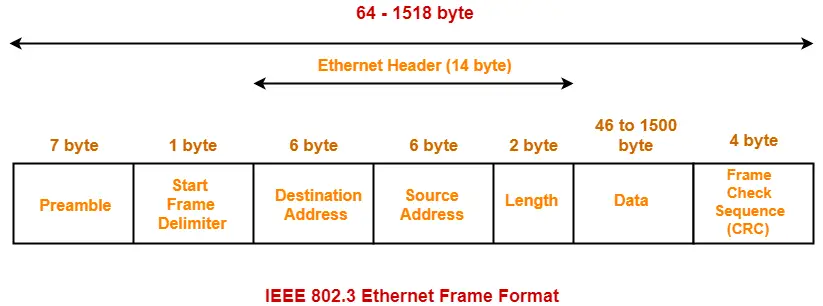
IEEE 802.3 defines the following Ethernet frame format-

1. Preamble-
- It is a 7 byte field that contains a pattern of alternating 0’s and 1’s.
- It alerts the stations that a frame is going to start.
- It also enables the sender and receiver to establish bit synchronization.
2. Start Frame Delimiter (SFD)-
- It is a 1 byte field which is always set to 10101011.
- The last two bits “11” indicate the end of Start Frame Delimiter and marks the beginning of the frame.
NOTES
|
3. Destination Address-
- It is a 6 byte field that contains the MAC address of the destination for which the data is destined.
4. Source Address-
- It is a 6 byte field that contains the MAC address of the source which is sending the data.
5. Length-
- It is a 2 byte field which specifies the length (number of bytes) of the data field.
- This field is required because Ethernet uses variable sized frames.
NOTES
|
The following three fields collectively represents the Ethernet Header–
- Destination Address (6 bytes)
- Source Address (6 bytes)
- Length (2 bytes)
Thus, Ethernet Header Size = 14 bytes.
6. Data-
- It is a variable length field which contains the actual data.
- It is also called as a payload field.
- The length of this field lies in the range [ 46 bytes , 1500 bytes ].
- Thus, in a Ethernet frame, minimum data has to be 46 bytes and maximum data can be 1500 bytes.
Minimum Length of Data Field
Minimum length of data packet = 2 x Propagation delay x Bandwidth
Maximum Length of Data Field
|
7. Frame Check Sequence (CRC)-
- It is a 4 byte field that contains the CRC code for error detection.
Advantages of Using Ethernet-
- It is simple to understand and implement.
- Its maintenance is easy.
- It is cheap.
Limitations of Using Ethernet-
Point-01:
- It can not be used for real time applications.
- Real time applications require the delivery of data within some time limit.
- Ethernet is not reliable because of high probability of collisions.
- High number of collisions may cause a delay in delivering the data to its destination.
Point-02:
- It can not be used for interactive applications.
- Interactive applications like chatting requires the delivery of even very small amount of data.
- Ethernet requires that minimum length of the data must be 46 bytes.
Point-03:
- It can not be used for client server applications.
- Client server applications require that server must be given higher priority than clients.
- Ethernet has no facility to set priorities.
Token Ring overcomes these limitations of Ethernet.
Important Concept-
For data transmission-
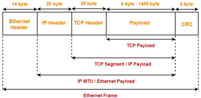
- TCP segment sits inside the IP datagram payload field.
- IP datagram sits inside the Ethernet payload field.

Next Article- Practice Problems On Ethernet
Get more notes and other study material of Computer Networks.
Watch video lectures by visiting our YouTube channel LearnVidFun.
Summary

Article Name
Ethernet in Networking | Ethernet Frame Format
Description
Ethernet in networking is a LAN technology. Ethernet frame format has several fields. Ethernet frame size range = [64 bytes, 1518 bytes]. Ethernet Header Size = 14 bytes. Ethernet Protocol is used to build wired LANs.
Author
Akshay Singhal
Publisher Name
Gate Vidyalay
Publisher Logo
