Ripple Carry Adder-
Before you go through this article, make sure that you have gone through the previous article on Ripple Carry Adder.
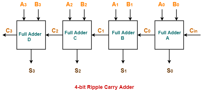
In Ripple Carry Adder,
- Each full adder has to wait for its carry-in from its previous stage full adder.
- Thus, nth full adder has to wait until all (n-1) full adders have completed their operations.
- This causes a delay and makes ripple carry adder extremely slow.
- The situation becomes worst when the value of n becomes very large.
- To overcome this disadvantage, Carry Look Ahead Adder comes into play.
In this article, we will discuss about Carry Look Ahead Adder.
Carry Look Ahead Adder-
- Carry Look Ahead Adder is an improved version of the ripple carry adder.
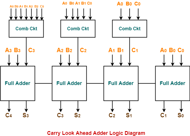
- It generates the carry-in of each full adder simultaneously without causing any delay.
- The time complexity of carry look ahead adder = Θ (logn).
Logic Diagram-
The logic diagram for carry look ahead adder is as shown below-
Carry Look Ahead Adder Working-
| The working of carry look ahead adder is based on the principle-
The carry-in of any stage full adder is independent of the carry bits generated during intermediate stages. |
The carry-in of any stage full adder depends only on the following two parameters-
- Bits being added in the previous stages
- Carry-in provided in the beginning
Now,
- The above two parameters are always known from the beginning.
- So, the carry-in of any stage full adder can be evaluated at any instant of time.
- Thus, any full adder need not wait until its carry-in is generated by its previous stage full adder.
Also Read- Full Adder Working
4-Bit Carry Look Ahead Adder-
Consider two 4-bit binary numbers A3A2A1A0 and B3B2B1B0 are to be added.
Mathematically, the two numbers will be added as-
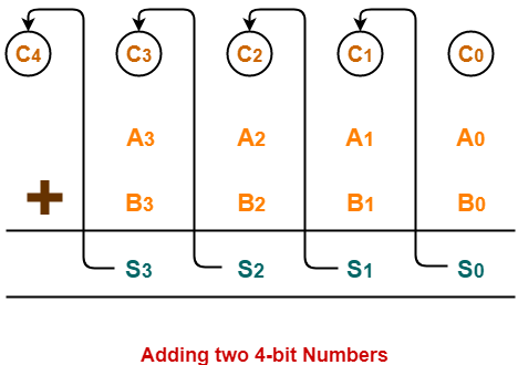
From here, we have-
C1 = C0 (A0 ⊕ B0) + A0B0
C2 = C1 (A1 ⊕ B1) + A1B1
C3 = C2 (A2 ⊕ B2) + A2B2
C4 = C3 (A3 ⊕ B3) + A3B3
For simplicity, Let-
- Gi = AiBi where G is called carry generator
- Pi = Ai ⊕ Bi where P is called carry propagator
Then, re-writing the above equations, we have-
C1 = C0P0 + G0 ………….. (1)
C2 = C1P1 + G1 ………….. (2)
C3 = C2P2 + G2 ………….. (3)
C4 = C3P3 + G3 ………….. (4)
Now,
- Clearly, C1, C2 and C3 are intermediate carry bits.
- So, let’s remove C1, C2 and C3 from RHS of every equation.
- Substituting (1) in (2), we get C2 in terms of C0.
- Then, substituting (2) in (3), we get C3 in terms of C0 and so on.
Finally, we have the following equations-
- C1 = C0P0 + G0
- C2 = C0P0P1 + G0P1 + G1
- C3 = C0P0P1P2 + G0P1P2 + G1P2 + G2
- C4 =C0P0P1P2P3 + G0P1P2P3 + G1P2P3 + G2P3 + G3
These equations are important to remember.
These equations show that the carry-in of any stage full adder depends only on-
- Bits being added in the previous stages
- Carry bit which was provided in the beginning
Trick To Memorize Above Equations-
As an example, let us consider the equation for generating carry bit C2.
There are three possible reasons for generation of C2 as depicted in the following picture-
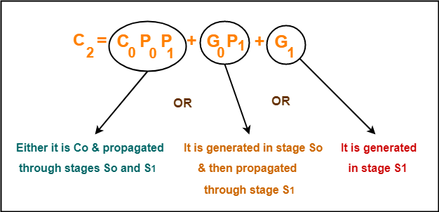
In the similar manner, we can write other equations as well very easily.
Implementation Of Carry Generator Circuits-
The above carry generator circuits are usually implemented as-
- Two level combinational circuits.
- Using AND and OR gates where gates are assumed to have any number of inputs.
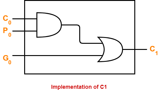
Implementation Of C1–
- The carry generator circuit for C1 is implemented as shown below.
- It requires 1 AND gate and 1 OR gate.
C1 = C0P0 + G0
Implementation Of C2–
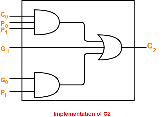
- The carry generator circuit for C2 is implemented as shown below.
- It requires 2 AND gates and 1 OR gate.
C2 = C0P0P1 + G0P1 + G1
Implementation Of C3 & C4–
Similarly, we implement C3 and C4.
- Implementation of C3 uses 3 AND gates and 1 OR gate.
- Implementation of C4 uses 4 AND gates and 1 OR gate.
Total number of gates required to implement carry generators (provided carry propagators Pi and carry generators Gi) are-
- Total number of AND gates required for addition of 4-bit numbers = 1 + 2 + 3 + 4 = 10.
- Total number of OR gates required for addition of 4-bit numbers = 1 + 1 + 1 + 1 = 4.
General Formula-
The following formula is used to calculate number of gates required for evaluating all carry bits-
|
For a n-bit carry look ahead adder to evaluate all the carry bits, it requires-
|
Advantages of Carry Look Ahead Adder-
The advantages of carry look ahead adder are-
- It generates the carry-in for each full adder simultaneously.
- It reduces the propagation delay.
Disadvantages of Carry Look Ahead Adder-
The disadvantages of carry look ahead adder are-
- It involves complex hardware.
- It is costlier since it involves complex hardware.
- It gets more complicated as the number of bits increases.
To gain better understanding about Carry Look Ahead Adder,
Next Article- K Maps | Karnaugh Maps
Get more notes and other study material of Digital Design.
Watch video lectures by visiting our YouTube channel LearnVidFun.